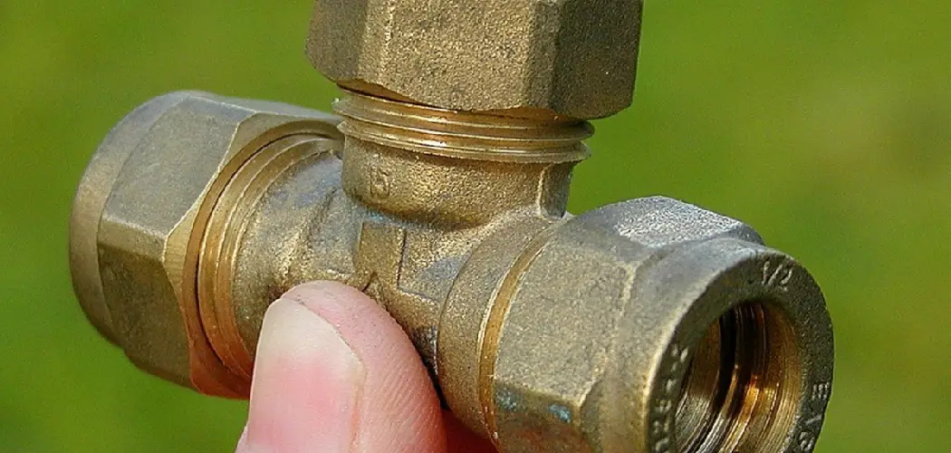
Flare fittings are essential components in plumbing and gas lines, designed to create a secure, leak-proof connection between pipes and tubing. These fittings often appear in high-pressure applications, such as refrigeration, air conditioning, and gas delivery systems, where reliable connections are critical for safety and efficiency. Accurate measurement of flare fittings is crucial, as improper sizing can lead to leaks, system inefficiencies, and potential hazards.
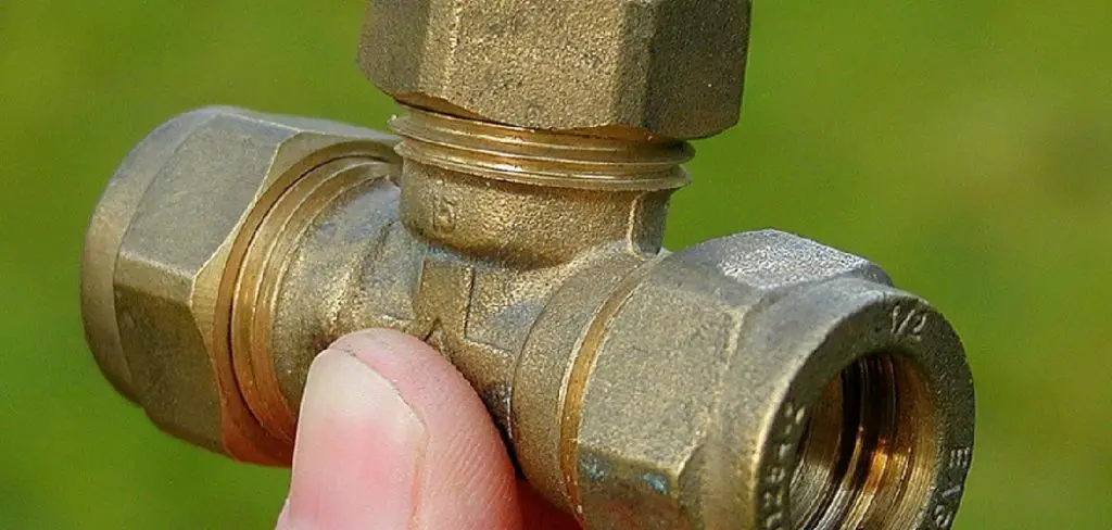
Understanding how to measure flare fittings involves several key steps, including the identification of fitting types, gathering necessary tools, and employing precise measurement techniques.
This guide on how to measure flare fittings will provide you with a comprehensive overview, ensuring that you achieve the correct fit and maintain the integrity of your plumbing or gas line system. By following these steps, you can prevent leaks and ensure that your connections remain secure and effective.
Identify the Fitting Type
Before measuring flare fittings, it’s essential to identify the specific type of fitting you’re dealing with. Common types of flare fittings include SAE (45-degree flare) and JIC (37-degree flare). The SAE 45-degree flare is often used in plumbing and automotive applications, while the JIC 37-degree flare is predominantly found in hydraulic and gas lines.
Next, consider the material and use of the flare fitting. Flare fittings can be made from various materials such as brass, stainless steel, or even aluminum, and the choice of material often depends on the application. For instance, brass fittings are commonly used in plumbing due to their resistance to corrosion, while stainless steel fittings are preferred in industrial settings for their durability and strength. By accurately identifying the type and material of the flare fitting, you can proceed with confidence, ensuring that the correct measurements are taken and the fitting is suitable for your specific needs.
Gather Necessary Tools
To accurately measure flare fittings, you’ll need a few essential tools. A caliper or ruler is crucial for measuring the diameter of the fitting, ensuring precise sizing. A thread pitch gauge will help determine the thread count and type, which is vital for compatibility with other components. A fitting reference chart (optional) can be handy to cross-reference measurements and verify fitting specifications.
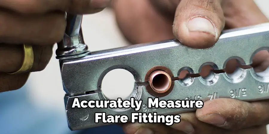
Finally, having a pen and paper for notes allows you to record your measurements and observations systematically. Collect these tools before beginning the measurement process to ensure accuracy and efficiency.
How to Measure Flare Fittings: Measure the Flare Angle
1. Identify the Flare Angle
The first step in measuring the flare angle is to identify whether your fitting is an SAE or JIC type. SAE fittings typically have a 45-degree flare, which is commonly used in plumbing and automotive applications. On the other hand, JIC fittings have a 37-degree flare, predominantly found in hydraulic and gas lines.
2. Using a Protractor or Flare Gauge
To ensure precision in measuring the flare angle, it’s advisable to use a protractor or a specialized flare gauge. Follow these steps:
- Place the Fitting on a Flat Surface: Ensure that the fitting is stable and positioned correctly.
- Align the Protractor or Flare Gauge With the Fitting’s Flare: Position the tool so that it is in direct contact with the flare surface.
- Determine the Angle by Comparing It to the Markings on the Gauge or Protractor: Carefully note the alignment and read the angle indicated by the tool. This comparison will help you verify whether the fitting is a 37-degree or 45-degree flare.
3. Visual Inspection
If you don’t have access to specialized tools, you can still perform a basic inspection:
- Visually Inspect and Compare the Fitting With Known Angles: Compare your fitting against known angles. A 45-degree flare is more pronounced and steeper than a 37-degree flare, which is more subtle.
- Use a Reference Fitting: If possible, compare your fitting with a known 45-degree or 37-degree fitting to make a visual judgment.
By carefully identifying the flare angle, you can ensure that your fittings are compatible with your application and maintain the integrity of your system.
4. Measure the Fitting Diameter
Accurately measuring the diameter of flare fittings, both outer and inner, as well as the thread size, is crucial for ensuring compatibility and a secure fit. Follow these detailed steps to obtain precise measurements:
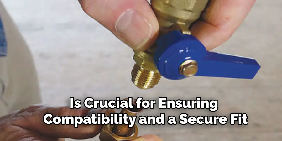
1. Outer Diameter (OD)
- Use a Caliper or Ruler to Measure the Outer Diameter of the Male Fitting or the Outer Edge of the Flare:
- Start by ensuring that the caliper or ruler you are using is in good condition and calibrated for accurate measurement.
- Position the caliper or ruler perpendicular to the fitting’s surface.
- Gently close the jaws of the caliper around the outer edge of the male fitting or the flare until they touch the fitting without compressing it.
- Ensure the Caliper is Perpendicular to the Fitting for an Accurate Measurement:
- Holding the caliper at a perpendicular angle to the fitting prevents measurement errors caused by tilting or angling the tool.
- Record the Measurement in Inches or Millimeters:
- Once you have the caliper or ruler in place, read the measurement displayed on the tool.
- Write down the measurement carefully, specifying whether it is in inches or millimeters.
2. Inner Diameter (ID)
- For Female Fittings, Measure the Inner Diameter Where the Male Fitting Would Be Inserted:
- Similar to measuring the outer diameter, use a caliper or ruler that is precise and properly calibrated.
- Insert the caliper’s jaws into the opening of the female fitting.
- Place the Caliper or Ruler Inside the Fitting and Measure Across the Opening:
- Make sure the caliper or ruler extends fully across the inner diameter and touches both inner walls of the fitting.
- Record the Measurement Accurately:
- After positioning the tool correctly, read the displayed measurement.
- Note this measurement clearly, including whether it is in inches or millimeters.
3. Thread Size
- Use a Thread Pitch Gauge to Measure the Threads Per Inch (Tpi) or the Thread Pitch:
- A thread pitch gauge is essential for determining the specific thread pattern of the fitting.
- Align the gauge’s teeth with the threads of the fitting.
- Align the Gauge With the Threads and Ensure a Snug Fit to Count the Threads:
- Fit the gauge snugly against the threads to ensure an accurate count.
- For Metric Fittings, Measure the Distance Between Threads (Pitch) in Millimeters:
- Instead of threads per inch, metric fittings use pitch, which measures the distance between the threads.
- Measure the pitch accurately by holding the gauge in line with the fitting’s threads.
- Record the Thread Size and Pitch:
- Write down the threads per inch (TPI) or the pitch measurement.
- Document any additional relevant information, such as the thread type.
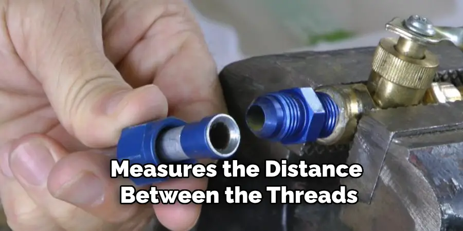
By following these steps meticulously, you can ensure that your measurements are accurate and your flare fittings are compatible with your system requirements.
5. Compare Measurements with Standards
Use a Fitting Reference Chart
After obtaining precise measurements, the next crucial step is to compare them with a fitting reference chart. Fitting reference charts help you identify the fitting size and type by cross-referencing the measurements you have taken. These charts are often available from manufacturers or can be found through various online resources.
- Compare Your Measurements With a Fitting Reference Chart to Identify the Fitting Size and Type: Locate the section of the chart corresponding to your type of fitting (SAE, JIC, etc.) and match your measurements to the listed sizes. Ensure that the outer diameter (OD), inner diameter (ID), and thread size align with the standard sizes provided in the chart.
- Reference Charts Are Available From Manufacturers or Online Resources: Utilize charts from reputable sources, as manufacturers often provide detailed and specific information for their products.
Verify Compatibility
Once you have identified the fitting size and type, the next step is to ensure compatibility with your intended application. This involves verifying that all measured aspects of the fitting meet the specifications required by your system.
- Ensure the Measured Fitting Matches the Specifications Required for Your Application: Double-check your application’s requirements in terms of flare angle, diameter, and thread size. This ensures that the fitting will perform reliably under operating conditions.
- Double-check the Flare Angle, Diameter, and Thread Size to Confirm a Proper Fit: Reassess each measurement to avoid any potential errors. Confirm that the flare angle aligns with either the 37-degree or 45-degree standard, as appropriate. Verify that both the outer and inner diameters, as well as the thread size, correspond perfectly with the reference chart and the system requirements. This thorough verification process helps prevent leaks, ensure safety, and maintain the integrity of your system.

Final Check and Documentation
Recheck Measurements
Before finalizing the process, it is crucial to double-check all measurements for accuracy. Re-measure the outer and inner diameters, as well as the thread size, using your trusted caliper, ruler, or thread pitch gauge. Ensure that your tools are still properly calibrated and that each measurement is taken with precision. This step helps eliminate any potential errors that could compromise the fitting performance.
Document Results
Accurate documentation of your findings is essential for future reference. Write down each measurement, clearly specifying whether it is in inches or millimeters. Include details about the fitting type, size, and thread specifications. Keeping thorough records allows you to replicate successful fittings, troubleshoot issues more effectively, and maintain a log for quality control purposes.
Test Fit
Whenever possible, conduct a test that fits the corresponding counterpart. This involves connecting the flare fitting to its matching part to verify a secure and leak-proof connection. Carefully inspect the fit to make sure there are no gaps, misalignments, or signs of potential leakage. Conducting a test fit ensures that the fitting meets all required specifications and will perform reliably under operating conditions.
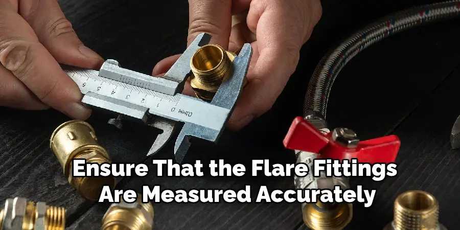
By following these steps, you can ensure that the flare fittings are measured accurately, documented thoroughly, and function properly within your system.
Conclusion
In the process of learning how to measure flare fittings, it is essential to follow a detailed and systematic approach. Start by identifying the type of fitting—whether it’s SAE, JIC, or another standard—since this determines the specific measurements required. Measure the flare angle using a protractor or angle gauge to ensure it matches either the 37-degree or 45-degree standard. Next, a caliper or ruler is used to measure the outer and inner diameters, and a thread pitch gauge is employed to determine the thread size and pitch. Compare these measurements with a fitting reference chart to confirm the size and type, and ensure compatibility with your application by rechecking all specifications.
Accurate measurements are crucial to ensure the flare fittings’ proper fit and functionality. Using high-quality tools can greatly enhance measurement precision, minimizing the risk of errors that could compromise system integrity. Consulting with professionals can provide valuable guidance and assurance if you are unsure about any step.

