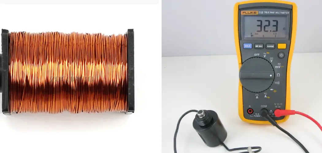
Testing a solenoid coil is a fundamental process for diagnosing issues in various electromechanical systems, including automotive starters, industrial machinery, and irrigation valves. A solenoid coil, when energized, generates a magnetic field that triggers mechanical movement, making it a vital component in these systems. Ensuring its proper function is crucial for the overall performance and reliability of the equipment. The testing process involves several key steps: visually inspecting the coil for physical damage, using a multimeter to measure resistance and continuity, and checking the voltage supply.
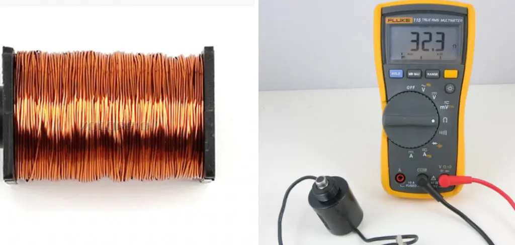
By methodically assessing these parameters, you can identify whether the coil is functioning correctly or if there are underlying issues such as short circuits, open circuits, or insufficient magnetic force. This guide will provide a comprehensive guide on how to test a solenoid coil, step-by-step instructions for testing, and tips for interpreting the results, equipping you with the knowledge to maintain and troubleshoot solenoid coils effectively.
The Importance of Solenoid Coils
Solenoid coils play a critical role in the efficient functioning of various electromechanical systems. Their ability to convert electrical energy into mechanical motion makes them indispensable in a wide range of applications. In automotive systems, solenoid coils are integral to the operation of starter motors, fuel injectors, and solenoid valves, ensuring reliable engine performance and fuel efficiency. In industrial settings, they are used in automation processes, enabling precise control of machinery and fluid systems.
Solenoid coils are also essential in everyday devices such as door locks, irrigation systems, and even telecommunication equipment. The reliable operation of solenoid coils ensures the seamless performance of these systems, highlighting their importance in both industrial and consumer applications.
10 Methods How to Test a Solenoid Coil
1. Visual Inspection
A visual inspection is the first step in testing a solenoid coil, as it can reveal obvious signs of damage that might affect performance. Begin by disconnecting the solenoid from its power source and any connected equipment. Examine the coil and surrounding components for physical damage such as burns, cracks, corrosion, or discoloration, which could indicate overheating or electrical faults. Check for loose or broken connections and ensure that the coil’s insulation is intact. While a visual inspection won’t diagnose all potential issues, it can quickly identify visible problems that need immediate attention.
2. Resistance Measurement
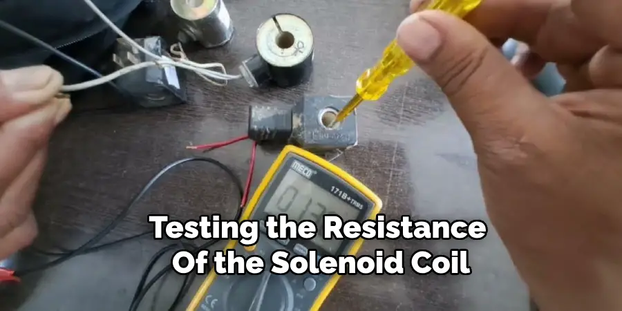
Measuring the resistance of a solenoid coil is a fundamental test to determine its electrical health. Use a digital multimeter set to the ohms (Ω) scale for this test. First, disconnect the solenoid from the power supply and ensure the coil is not connected to any other circuit components. Place the multimeter probes across the coil terminals and record the resistance reading. Compare this value to the manufacturer’s specifications for the specific solenoid. A significantly higher or lower resistance than specified can indicate a problem such as an open circuit or shorted turns within the coil.
3. Continuity Test
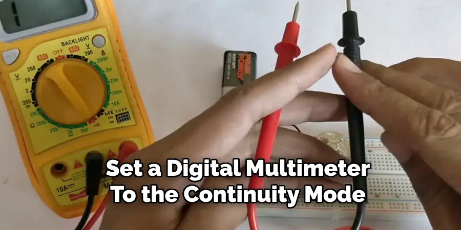
A continuity test is essential for verifying that there is an uninterrupted electrical path through the solenoid coil. Set a digital multimeter to the continuity mode, which often features an audible alert. Disconnect the solenoid from its power source and isolate the coil from the circuit. Place the multimeter probes on the coil terminals. If the multimeter beeps or shows a continuity reading, the coil is electrically continuous. A lack of continuity indicates an open circuit, meaning the coil is broken or there is a poor connection somewhere in the coil winding.
4. Insulation Resistance Test
Testing the insulation resistance of a solenoid coil helps ensure that the coil’s windings are properly insulated from each other and from the coil’s core, preventing short circuits. Use an insulation resistance tester, also known as a megohmmeter, for this test. Disconnect the solenoid and ensure it is not powered. Connect one probe to a coil terminal and the other to the coil housing or core. Apply the test voltage (typically 500V or 1000V) as specified by the tester. A high resistance reading indicates good insulation, while a low reading suggests deteriorated insulation or potential short circuits.
5. Voltage Drop Test
The voltage drop test measures the voltage lost across the solenoid coil and can help identify issues related to excessive resistance or poor connections. To perform this test, connect the solenoid to its power supply. Set a digital multimeter to the voltage (V) scale and measure the voltage across the coil terminals while the solenoid is energized. Compare the measured voltage drop to the expected value based on the supply voltage and the solenoid’s rated operating voltage.
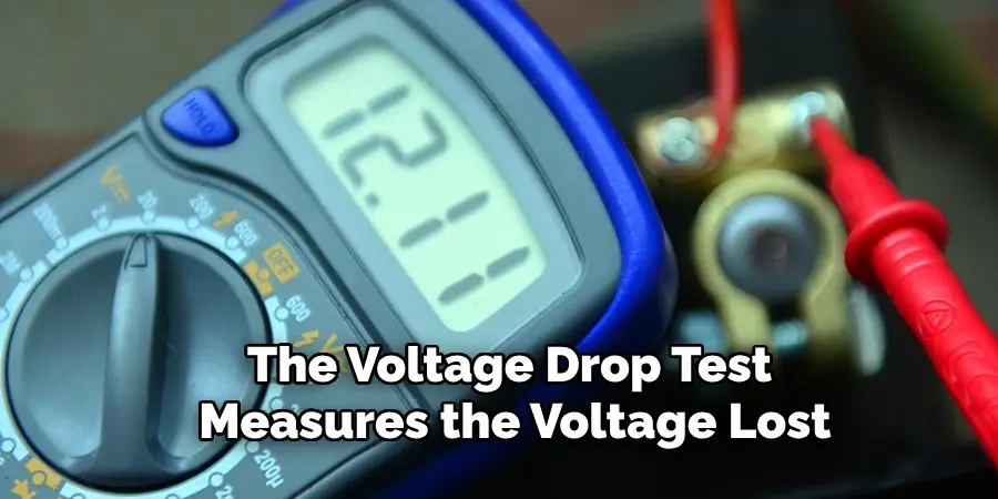
A significant deviation from the expected value may indicate issues such as increased resistance or faulty connections within the coil.
6. Current Draw Test
Measuring the current draw of a solenoid coil provides insights into its operational performance and can help detect problems such as shorted turns or excessive load. To conduct this test, use a digital multimeter set to the current (A) scale. Connect the solenoid to its power supply and ensure the multimeter is connected in series with one of the coil terminals. Energize the solenoid and observe the current reading. Compare this value with the manufacturer’s specifications for the solenoid. A higher than normal current draw can indicate shorted turns within the coil, while a lower than normal current draw might suggest an open circuit or increased resistance.
7. Inductance Measurement
Measuring the inductance of a solenoid coil can help determine its condition and performance characteristics. Use an LCR meter (which measures inductance, capacitance, and resistance) for this test. Disconnect the solenoid from its power supply and isolate the coil. Connect the LCR meter probes to the coil terminals and select the inductance measurement mode. Record the inductance value and compare it to the manufacturer’s specifications. Significant deviations from the expected inductance can indicate problems such as shorted turns, changes in the coil’s core material, or physical damage to the coil windings.
8. Functional Test
A functional test involves operating the solenoid in its intended application to verify its performance. Reconnect the solenoid to its power supply and any associated control circuitry. Energize the solenoid and observe its mechanical movement or the operation of the connected device. Ensure the solenoid actuates correctly, responds to control signals, and returns to its original position when de-energized. Listen for any unusual noises such as buzzing or humming, which could indicate electrical or mechanical issues. A successful functional test confirms that the solenoid operates as expected under real-world conditions.
9. Coil Resistance to Ground Test
Testing the resistance of the solenoid coil to ground helps detect potential grounding issues or insulation failures. Use a digital multimeter set to the resistance (Ω) scale for this test. Disconnect the solenoid from the power supply and ensure it is isolated from the circuit. Connect one probe to a coil terminal and the other to the coil’s metal housing or ground. Measure the resistance and compare it to the manufacturer’s specifications. Ideally, the resistance to ground should be very high, indicating good insulation. A low resistance reading suggests a potential short circuit to ground or compromised insulation.
10. Thermal Imaging
Thermal imaging is a non-invasive method to assess the thermal performance and detect hotspots in a solenoid coil. Use a thermal imaging camera to capture the temperature profile of the solenoid during operation. Energize the solenoid and allow it to reach its normal operating temperature. Scan the solenoid with the thermal camera and observe the temperature distribution. Uniform heating indicates normal operation, while hotspots can indicate localized overheating, shorted turns, or poor electrical connections. Analyzing the thermal images can help diagnose issues that may not be apparent through other testing methods.
Things to Consider When Testing Solenoid Coils
When testing solenoid coils, several factors and precautions should be taken into account to ensure accurate results and the safety of personnel and equipment. Here are some key considerations:
- Safety Precautions: Always ensure that the solenoid is disconnected from its power source before performing any tests. This can prevent electrical shock or accidental activation, which could result in injury or equipment damage.
- Correct Equipment: Use the appropriate testing equipment for the specific tests you’re conducting. Ensure that the multimeter, insulation resistance tester, megohmmeter, or LCR meter is calibrated and functioning correctly to avoid inaccurate readings.
- Environmental Conditions: Conduct tests in a stable environment where temperature, humidity, and other conditions are within acceptable ranges. Extreme conditions can affect both the solenoid’s performance and the accuracy of test results.
- Manufacturer Specifications: Always compare your test results against the solenoid’s manufacturer specifications. This will help identify any deviations from expected performance parameters and facilitate accurate diagnosis of potential issues.
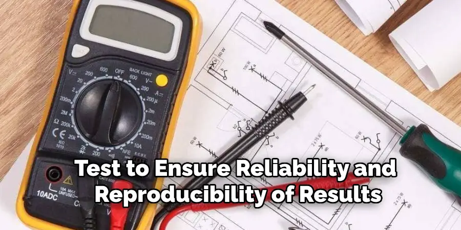
- Consistent Testing Procedures: Follow a consistent method for each test to ensure reliability and reproducibility of results. Varying procedures can lead to inconsistent data that may complicate troubleshooting efforts.
Conclusion
Testing solenoid coils comprehensively involves a combination of electrical, mechanical, and thermal assessments to ensure their proper functioning and reliability. Each method described above offers unique insights into the condition of the solenoid coil and can help identify potential issues before they lead to system failures. From basic visual inspections to advanced thermal imaging, these testing methods provide a robust toolkit for diagnosing and troubleshooting solenoid coils in various applications.
By following these comprehensive guidelines on how to test a solenoid coil, technicians and engineers can maintain the integrity and performance of electromechanical systems, ensuring optimal operation and longevity of solenoid components.

